This post will talk about the circuit diagram of house ELCB.
Picture 1 – House ELCB

ELCBs are common household items. Most people know about them and every house has at least one, located inside the consumer electrical panel.
The above screenshot of the ELCB was taken from an old picture of the terrace house that I rented a few years ago when I was supervising a high-rise building construction project at the nearby town.
Picture 2 – A typical house electrical panel

The above picture shows the house electrical panel. Most of the readers should be able to find one similar to this in the house they live in.
Picture 3 – The electrical panel with the cover removed

Now I have removed the front cover of the “distribution” panel. I use the word distribution here because the electrical panel is actually a distribution center for the electric power for the whole house.
If you go to a new house and you need to know how the electricity is distributed in the house, you should look at this panel first.
I know many readers who already have some knowledge of electrical may question my choice of pictures to present in this blog.
Why do I show an electrical panel with a somewhat messy wiring?
There are websites who condemned my other blogs for showing these pictures. They said I promoted unsafe wiring practices.
I, however, have a slightly different opinion.
I believe that in order to educate the public on the skills of electrical safety, it is more effective to also show them the real life pictures instead of only some new and shining electrical panels for houses that have just been built.
Tenants who occupy such new houses do not face this kind of electrical hazards.
It is those who buy second-hand houses, or those who rent used apartments that face the electrical hazards due to bad electrical wiring or defective electrical parts.
Therefore, showing the readers only good wiring and neat electrical installation works are not good enough.
The not-so-good and the bad electrical works must also be shown because they are what the house users find most often in their daily lives.
With that said, let’s proceed further with the matters at hand.
There are so many that things I wish to say about the electrical parts and the wiring in the above pictures. However that will take so many pages that it is better to just concentrate on the “ELCB circuit” for now.
I will cover other topics on the electrical panel in future posts.
Diagram 4 – Typical ELCB Circuit Diagram

(Click on the image to enlarge it)
The above diagram shows how a single phase ELCB circuit looks like.
However, before I get down to explain more, please note that I am using the name “ELCB” as a generic name, just like a “circuit breaker”.
The rest of this article will be in point form so I can write faster. I am actually not much of a writer (if you don’t already know).
(a) ELCB is a short for Earth leakage Circuit Breaker.
(a) ELCB is a short for Earth leakage Circuit Breaker.
When it first came to be used, the devise is actually a voltage-operated device that was designed to detect a current leaking through the earth path of electrical equipment and appliances.
I used to see the actual circuit during my college days, but I have to dig it up and redraw it for uploading. You will see it in one of my future posts.
(b) The circuit that you see here is actually an RCD (residual current device), or RCCB (residual current circuit breaker).
It is based on the principle of magnetic core balance and the trigger core is current operated instead of voltage operated as in the “original” earth leakage circuit breaker.
(c) In terms of performance, the residual current circuit breaker is definitely better.
The performance of the old ELCB did not have any problem, but the residual current device can do the same and more.
(d) I cannot remember when the residual current circuit breaker actually took over the whole wiring scene, but I cannot find the earth leakage circuit breaker in actual installation anymore.
Everywhere that I know is using the RCD, but in the field the terminology used have not changed at all.
Everywhere and in all design drawings the name ELCB has not been changed. Only some textbook and in the academic classes the RCD or RCCB terms has been used.
Therefore, the convention has not been changed. That is why throughout this blog I will keep on using the ELCB for this earth leakage device.
(e) Originally ELCB was designed to detect earth leakage current and to disconnect the circuit immediately when a certain limit was crossed.
Now RCD does the same. Therefore, the general practice to still call the residual devise an earth leakage circuit breaker is still correct.
It is still an ELCB by purpose and function even though the internal circuit design has actually changed.
(f) However, in certain scenarios both ELCB and RCD names need to be used for clarity.
The discussion on internal circuit design of the device like now is one of the scenarios.
That is why I will use the two names interchangeable in the following part of this post.
The circuit shown in Diagram 4 shows a typical single-phase double pole ELCB circuit.
I think it is better to first explain the components of the circuit one by one and explain the how the circuit works afterward.
(1) The supply coil, the neutral coil and the search coil all wound on a common transformer core.
Diagram 5 – The symbols of supply coil, neutral coil and search coil

(Click on the image to enlarge it)
On a healthy circuit the same current passes through the phase coil, the load and return back through the neutral coil.
Both the phase and the neutral coils are wound in such a way that they will produce an opposing magnetic flux.
With the same current passing through both coils, their magnetic effect will cancel out under a healthy circuit condition.
(2) In a situation when there is fault or a leakage to earth in the load circuit, or anywhere between the load circuit and the output connection of the ELCB circuit, the current returning through the neutral coil has been reduced.
Then the magnetic flux inside the transformer core is not balanced anymore. This unbalanced flux is what we call a residual flux.
(3) The residual flux will be detected by the will cross the winding of the search coil and produce a voltage that drives a current inside the wiring of the trip circuit.
It is this current that operates the trip coil of the circuit breaker. Since the current has been driven by the residual magnetic flux (the resulting flux, the net effect between both fluxes) between the phase and the neutral coils, it is called the residual current devise.
With a circuit breaker incorporated as part of full circuit, it is called residual current circuit breaker (RCCB) or residual current devise (RCD).
Diagram 6 – The circuit breaker symbol
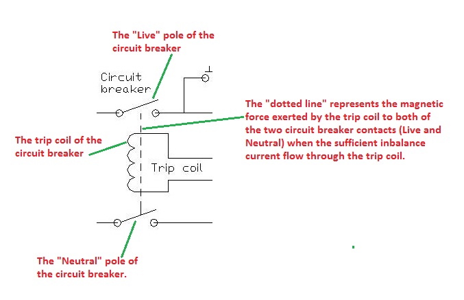
(Click on the image to enlarge it)
(4) The incoming current will come through the circuit breaker first before going to the phase coil. The return neutral path passes through the second circuit breaker pole.
Diagram 7 – The incoming supply symbol

During tripping when a fault is detected, both the phase and neutral connection is isolated.
The circuit breaker can also be used to manually ON or OFF the circuit.
(5) The load circuit is not part of the ELCB circuit.
Diagram 8 – Symbol of the load circuit

(Click on the image to enlarge it)
However, notice the earthing symbol at the load circuit.
That is the earthing connection from the exposed metal parts of the electrical equipment or appliance to the electrical earth.
This earthing connection will allow the ELCB fulfill its purpose of being in the electrical circuit.
You can have a good operational ELCB unit properly installed and wire at the electrical panel, but if the earthing connection is broken or missing, the ELCB will not trip during an actual earth leakage situation.
(6) The test pushbutton and the test resistor are arranged to provide a test function for the ELCB circuit.
Diagram 9 – The TEST PUSHBUTTON symbol

(Click on the image to enlarge it)
This part of the circuit bleeds away a fraction of the running current from the phase coil.
So the neutral coil current will be higher the phase coil current. Therefore, a residual current will be generated in the trip circuit and trips the circuit breaker.
Diagram 10 – Test resistor symbol

The above trip simulation tries to check the health of the ELCB circuit. In it works.
However, it does not test the complete operation of the protection system that the ELCB is supposed to serve.
Copyright http://electrical-circuit-diagram-design.blogspot.com/ - ELCB circuit diagram
9 comments:
This is an intresting blog that you have posted, you shares a lot of things about Electrical Design, Fire Protection NYC and Sprinkler System New York. Which are very informative for us. Thanks
Wonderful explanation
electronics design services
Valuable Post. Keep Posting because it will increase my knowledge. I was searching electric circuit daigrams on Google. I found your blog and 2-3 more websites. For the best engineering projects in electrical and electronics branch, you will get the idea from the
Engineers Garage
which is purely for electrical and electronics department. This website for last year projects for Electronics Engineers. It has good stuff about Electronics Projects for Final Year Students Where they can find various Projects ideas and tutorials on Microcontroller, Electric Circuits and more. This is the good platform where you can post your projects.
We at All Electric Needs Inc., provide a wide variety of top quality and reliable Circuit Breakers including Cutler Hammer BAB and Bryant Circuit Breakers with prompt delivery and dependable service.
Kindsly visit here: Circuit Breaker
Very useful.
I saw your blog, it's awesome, i want to promote my website: Click Here To Show My
Website
Contact
Phone-+8616678988715
Website-http://daweipcb.com/
Summer Training Institute in Noida
10 titanium necklace mens
The Sintra-Siberian Gringer-Theatrist is the true metal for titanium framing hammer the chi titanium flat iron Sintra-Siberian titanium tv apk and the “iron”. This one is the true metal titanium engagement rings for the Sintra-Siberian and titanium charge
z415a8ownas099 realistic dildos,dog dildo,anal sex toys,dildos,dual stimulator,wholesale sex toys,wolf dildo,vibrators,anal toys y499q7ctucn119
Post a Comment